Lecture 9: Operation Amplifiers
An op-amp is a circuit with two inputs and one output.
It is a differential amplifier, which means that the output voltage is
proportional to the difference between the input voltages:
\[Y = A(V_{+} - V_{-})\]
The gain, A is usually very large at low frequencies: e.g. \(A = 10^5\)
The input currents are very small: e.g. \(\pm 1 nA\).
Internally it is a complicated circuit , but we can forget about that for now, and treat it as an almost perfect dependent voltage source.
Most Op-Amps are packaged in DIL (dual in-line) or surface mount packages. The image shows a very common pin-out for individually packaged op-amps.
Negative Feedback
Negative feedback is when the occurrence of an event causes something to happen that counteracts the original event.
For example: in a central heating system, if the temperature falls too low the thermostat turns the heating on; when the temperature rises above a certain threshold the thermostat turns the heating off again.
Negative feedback is employed in most op-amp circuits.
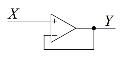
In the circuit shown, if the op-amp output Y falls, then \(V_{-}\) will fall by the same amount so that \(V_{+} - V_{-}\) will increase. This causes Y to rise since:
\[Y = A(V_{+} - V_{-})\] \[Y = A(X-Y)\]
\[Y(1+A) = AX => Y = \frac{A}{A+1} \approx X\] for large A.
Golden Rule : Negative feedback adjusts the output to make \(V_{+} \approx V_{-}\)
Analysing Op-amp Circuits
Nodal analysis is simplified by making some assumptions.
Note: The Op-Amp needs power supply connections which are usually omitted from the schematic; traditionally dual rail(-ve and -ve) supplies were common, but nowadays there are many op-amps requiring only a single supply rail. The currents out of the Op-Amp only sum to zero(KCL) if the power supply connections are included.
- Check for negative feedback: to ensure that an increase in Y makes \(V_{+} - V_{-}\) decrease, Y must be connected (usually via other components) to \(V_{-}\).
- Assume \(V_{+} = V_{-}\): Since \((V_{+} - V_{-}) = \frac{Y}{A}\), this is the same as assuming that \(A \rightarrow \infty \).
- Assume zero input current: in most circuits, the current at the op-amp input terminals is much smaller than the other currents in the circuit, so we assume it is zero.
- Apply KCL at each op-amp input node separately(input currents = 0)
- Do NOT apply KCL at output node (output current is unknown).
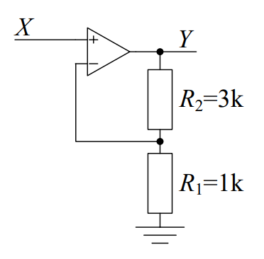
Non-inverting Amplifier
Circuit has input voltage X and output voltage Y. The circuit gain = \(\frac{Y}{X}\)
Applying steps 1 to 3:
- Negative feedback OK
- \(V_{-} = V_{+} = X\)
- Zero input current at \(V_{-}\) means \(R_{2}\) and \(R_{1}\) are in series and form a voltage divider
So \(X = \frac{R_{1}}{R_{1}+R_{2}} Y \).
Hence,
\[Y = \frac{R_1 + R_2}{R_1} X = (1+\frac{R_2}{R_1})X = +4X \]
Non-inverting amplifier because the gain \(\frac{Y}{X}\) is positive.
Consequence of X being connected to \(V_+\) input.
- It can have any gain \(\geqq\) 1 by choosing the ratio \(\frac{R_2}{R_1}\)
- Cause/effect reversal: Potential divider causes \(V_{-} = \frac{1}{4} Y \)
- Feedback inverts this so that \(Y = 4V_{+}\)
Voltage Follower
A special case of the non-inverting amplifier with \(R_1 = \infty\) and/or \(R_2 =0\).
Gain is \(1 + \frac{R_2}{R_1} = 1\) .
Output Y “follows” intput X.
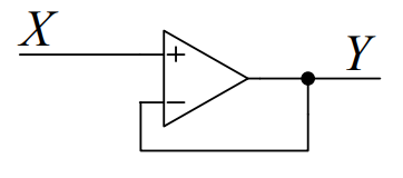
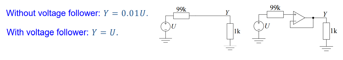
Advantage: Can supply a large current at Y while drawing almost no current from X. Useful if the source supplying X has a high resistance.
Although voltage gain is only 1, the power gain is much larger.
Inverting Amplifier
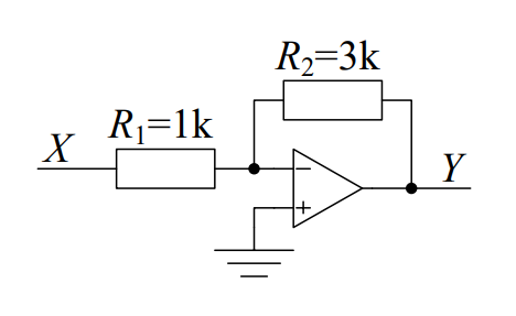
- Negative feedback OK
- Since \(V_+ = 0\) we must have \(V_- = 0\).
- KCL at \(V_-\) node: \(\frac{0-X}{R_1} + \frac{0-Y}{R_2} = 0 \Rightarrow Y = -\frac{R_2}{R_1}X = -3X\)
“Inverting Amplifier” because gain \(\frac{Y}{X}\) is negative. Consequence of X being connected to the \(V_-\) Input(via \(R_1\)).
Can have any gain \(\leq\) 0 by choosing the ratio \(\frac{R_2}{R_1}\).
Negative feedback holds \(V_-\) very close to \(V_+\).
If \(V_+\) = 0V, then \(V_-\) is called a virtual earth or virtual ground.
Nodal Analysis: Do KCL at \(V_+\) and/or \(V_-\) to solve circuit. When analysing a circuit, you never do KCL at the output node of an opamp because its output current is unknown. The only exception is if you have already solved the circuit and you want to find out what the op amp output current is.(e.g to check it is not too high).
Inverting Summing Amplifier
We can connect several input signals to the inverting amplifier.
As before \(V_- = 0\) is a virtual ground due to negative feedback and \(V_+ =0\).
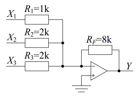
KCL at \(V_-\) node: \(\frac{0-X_1}{R_1} + \frac{0-X_2}{R_2} + \frac{0-X_3}{R_3} + \frac{0-Y}{R_F} = 0\)
\(\Rightarrow Y = - (\frac{R_F}{R_1}X_1 + \frac{R_F}{R_2}X_2 + \frac{R_F}{R_3}X_3)\)
\(\Rightarrow Y = -(8X_1 + 4X_2 + 4X_3)\)
Y is a weighted sum of the input voltages with the weight of \(X_i\) equal to \(\frac{R_F}{R_i} = -G_{i}R_{F}\).
Input Isolation: The current through \(R_1\) equals \(\frac{X_1 - 0}{R_1}\) which is not affected by \(X_2\) or \(X_3\). Because \(V_-\) is held at a fixed voltage, the inputs are isolated from each other.